
What’s the big deal with the battery?


Printed on one panel of the box it came in was:
TORNADO RC
2400 MAH TAMIYA
SSC: TRC-2400
and on another panel
TRC-2400 NIMH 2400 7.2V
So its main features are:
- Chemistry: Nickel metal hydride
- Nominal voltage: 7.2V
- Nominal capacity: 2400mAh
Surely it can’t be hard to incorporate this battery into the analysis?
Can’t we just
- use 7.2V for the maximum supply in our model of the motor, and
- divide the battery capacity in mAh by the current in mA to get the length of time the Grasshopper can operate on a single charge?
It’s not as easy as that.
First: The voltage at the battery terminals drops as capacity is used up.
Second: The voltage at the battery terminals and the capacity of the battery depend on the current it supplies.
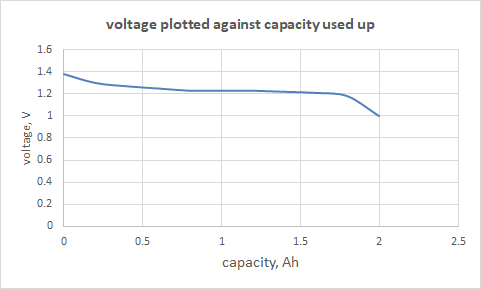
I found data on the web for a 2000mAh battery. It might not be exactly like the 2400mAh battery in the Grasshopper, but it should be near enough to demonstrate the principles. Plotting voltage (V) against capacity used up (Ampere-hours) makes it easy to compare the curves at various current-drains.

The voltage of this battery is approximately 1.2V at 0.2A. This is typical for a single cell Nimh battery; to get 7.2V requires six cells in series.
The horizontal line at 1.2V marks the nominal voltage. “Nominal” it certainly is: at 5A, for example, the curve barely keeps above 1V after the initial segment.
The horizontal line at 0.9V marks the usual cut-off voltage. This is the voltage where the battery is considered to be exhausted. 0.9V is typical of what I found on the web. It’s important not to run the battery too far down; over-exhaustion an cause damage. In this case, with a cut-off of 0.9V the capacity at 5A is barely 65% of that at 2A.
Below I have re-plotted the curves against time. It’ highlights the difference that current drain makes to duration.
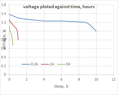
At ‘small’ currents the voltage profile is roughly consistent, so a capacity of 2000mAh if used up at 100 mA might give 20h of useful operation (2000mAh/100mA), or at 200mA it might be 10 h (2000mAh/200mA.
At large currents the voltage at the terminals is lower and the battery runs out of charge sooner.
A lower voltage means poorer performance;running out of charge sooner reduces the range.
From what I saw on the web, the discharge characteristics vary a lot between various battery designs, so I’m not going to worry about detail.
To find the Grasshopper’s top speed we need to know the current drain on the battery at the relevant conditions.
The motor and battery interact, and in use, the situation is further complicated by the speed controller. For the moment we will not include the controller, just the battery connected directly to the motor.
To model the interaction between battery and motor, I assumed that the shape of the curves was constant (it isn’t) and that the variation in voltage at the roughly parallel sections of the curves (1Ah, say) is due to the internal resistance of the battery (probably not very accurate either). Although this is not very accurate it will give us a useful starting point.
From the curves I estimated the internal resistance of the battery at 0.05ohm (which is typical of data on the web, so perhaps my assumptions weren’t so bad after all). For the six cells in series this gives 6*0.05ohm, or 0.3ohm.
It works like this.
The emf from the battery pushes a current around the circuit formed by the battery itself and the motor. The voltage at the battery terminals is reduced by the internal resistance, for example, if the current were 2A, the voltage drop would be 2*0.3V, or 0.6V, gving a voltage at the terminals of 7.2 – 0.6 = 6.6V.
This reduced voltage pushes a current through the motor, as we saw earlier in this series of blogs. There is a complication. The current through the motor depends on the voltage at the battery terminals; and the voltage at the battery terminals depends on the current through the motor.
This conundrum is just perfect for demonstrating the power of algebra.
the current I is given by:
I = (VT – K2*n)/(RM + RB)
I = (VB – I*RB – K2*n)/(RM + RB) Expanding this out
I*(RM+RB) = VB-I*RB – K2*n
I*RM + I*RB = VB – I*RB – K2*n collecting all the items with I
I*RM + I*RB + I*RM = VB – K2*n solving for I
I = (VB – K2*n)/(RM + 2*RB)
A spreadsheet gave me the answers I wanted for I.
Here are values at VB = 7.2V, with and without including internal resistance in the battery:
| condition | predicted current, A | predicted speed, km/h |
| battery internal resistance neglected | 28.8 (stall) | 22.4 |
| battery internal resistance = 0.3ohm | 8.47 (stall) | 19.3 |
| battery internal resistance = 0.3ohm | 1.51 (max speed) | 19.3 |
The effect of including the internal resistance is startling.

Here’s how these values compare with tests (motor connected the right way round).
calculated max speed, internal resistance 0.3ohm 19.3km/h
Measured max speed 19-20km/h
The agreement makes me feel good, but there are still quantities I have not tied down yet. We’ll get these later on.
